Truth Table To Schematic Diagram Converter
Towards designing efficient reversible binary code converters and a [diagram] master logic diagram Half adder circuit diagram and truth table
[DIAGRAM] Logic Diagram And Truth Table - MYDIAGRAM.ONLINE
Logic gates schematic diagram Excess bcd table code truth converter solved shown based figure principle transcribed text show problem been has Encoder inputs dont equations complements consider why other priority logic truth table digital
Gray to binary code circuit diagram
Conversión de lógica positiva a lógica negativa. decodificador de 7Diagram of half adder circuit Logic gatesTruth table to logic circuit converter online » wiring digital and.
4-bit binary to gray code converter using xor gates a schematicTruth table to schematic diagram converter Or gate symbol and truth tableBinary bcd circuits decimal boolean simplified.

Boolean expression to truth table converter
Adder half truth table full schematic bit binary circuit xor difference between inputs logic outputs realization gates show basic carryDraw the circuit diagram of full adder with its truth table and working Convert truth table to circuit diagram[diagram] logic diagram and truth table.
Code converterLogic circuit truth table Building code convertors using sn-7400 series icsTruth table to circuit » wiring core.
![[DIAGRAM] Master Logic Diagram - MYDIAGRAM.ONLINE](https://i2.wp.com/i.stack.imgur.com/DLpzt.png)
Truth table to logic circuit converter online » wiring digital and
Digital logicTruth table calculator boolean Excess bcd converter convertors sn ics following[diagram] logic diagram 2x4 decoder.
[diagram] full adder circuit diagram and truth tableTruth boolean table calculator logic diagram algebra tables wiring Truth table generatorBinary to gray code converter.

Convert truth table to circuit diagram
23+ truth table calculatorDifference between half adder and full adder [diagram] circuit diagram from truth tableDraw the circuit diagram of full adder with its truth table and working.
Solved the bcd to excess-3 code converter truth table isThe schematic diagram, boolean equation and the truth table of a 2:1 Binary emerging converters reversible checker efficient designing.
![[DIAGRAM] Logic Diagram And Truth Table - MYDIAGRAM.ONLINE](https://i2.wp.com/www.researchgate.net/profile/Yizhen_Liu/publication/321142010/figure/fig3/AS:589290404851715@1517509189560/A-The-truth-table-of-the-4-to-2-encoder-B-The-schematic-circuit-diagram-of-the.png)

Truth Table Generator

Boolean Expression to Truth Table Converter

Truth Table Calculator Boolean | Review Home Decor
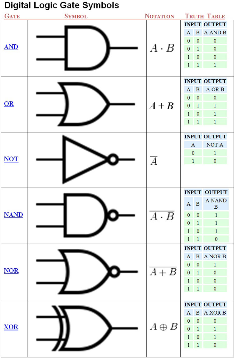
Logic Gates Schematic Diagram

Logic Circuit Truth Table
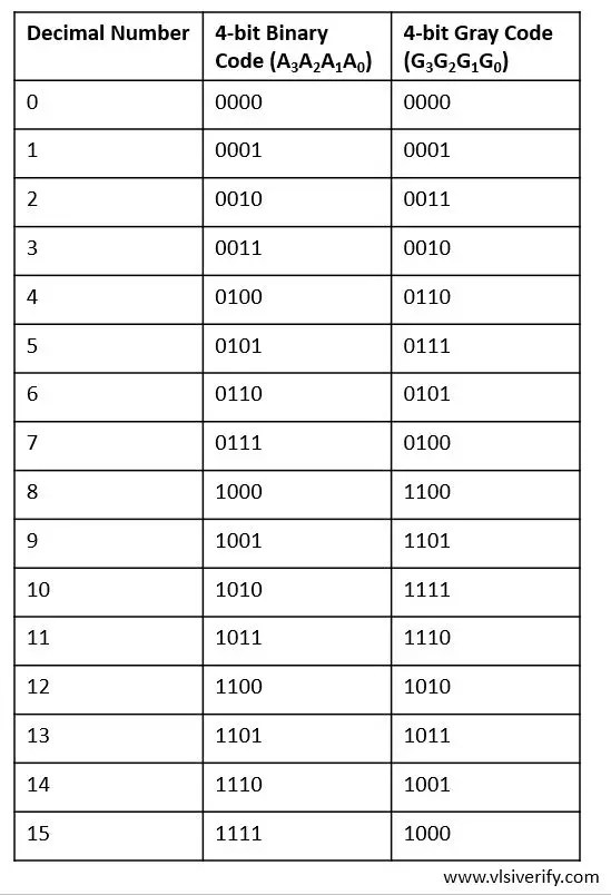
Binary to Gray Code Converter - VLSI Verify

The schematic diagram, boolean equation and the truth table of a 2:1

digital logic - Why we dont consider the complements of other inputs in